[OpenGL]Rendering Pipeline(渲染管线)流程概述
keywords: OpenGL Rendering Pipeline
Pipeline
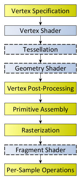
The OpenGL rendering pipeline works in the following order:
- Prepare vertex array data, and then render it
- Vertex Processing:
- Each vertex is acted upon by a Vertex Shader. Each vertex in the stream is processed in turn into an output vertex.
- Optional primitive tessellation stages.
- Optional Geometry Shader primitive processing. The output is a sequence of primitives.
- Vertex Post-Processing, the outputs of the last stage are adjusted or shipped to different locations.
- Transform Feedback happens here.
- Primitive Clipping, the perspective divide, and the viewport transform to window space.
- Primitive Assembly
The main primitive assembly stage just turns one stream of primitives into a stream of primitives that can be converted into fragments. So, it’s the last thing that happens before everything in the pipeline is converted into fragments (pixels).
There are different types of primitives, and each stage can take different types of primitives as inputs, and produce different types of primitives as outputs:- The tesselation evaluation shader takes patches as input. So you cannot put normal primitive assembly before the tesselation evaluation shader, since primitive assembly produces points, lines, or triangles.
- The geometry shader takes points, lines, triangles, lines with adjacency, or triangles with adjacency as input. So you cannot put normal primitive assembly before the geometry shader, because otherwise you would not be able to use lines or triangles with adjacency data.
- Scan conversion and primitive parameter interpolation, which generates a number of Fragments.
- A Fragment Shader processes each fragment. Each fragment generates a number of outputs.
注:Fragment Shader是GLSL的叫法,HLSL中叫做Pixel Shader。 - Per-Sample_Processing:
- Scissor Test
- Stencil Test
- Depth Test
- Blending
- Logical Operation
- Write Mask
参考资料:
Rendering Pipeline Overview
https://www.khronos.org/opengl/wiki/Rendering_Pipeline_Overview
图形渲染管线简介
https://zhuanlan.zhihu.com/p/70470309
What happens at the “Primitive assembly” stage in OpenGL
https://stackoverflow.com/a/61899548/1645289
Primitive Assembly
https://www.khronos.org/opengl/wiki/Primitive_Assembly
Shader
https://www.khronos.org/opengl/wiki/Shader#Stages
Primitive Assembly stage
Q: How does the GPU know in which order the vertices have to be processed? Maybe a triangle uses the first and the last vertex of the VBO, so primitive assembly stage would have to wait until the whole VBO is processed?
A: The order vertices were processed in is not particularly important by the time you arrive at primitive assembly; there is no order-dependence at the vertex shader level (the vertices could have all been processed in parallel for all you know). All you need to know is that the results of a vertex shader are appended to a special buffer called the post-transform cache.
A Geometry Shader (programmable primitve assembly) will fetch its input vertices from the post-transform cache, and it will do that in a specific order. Given a traditional FIFO implementation of the post-transform cache, order dictates cache replacement and strip-based primitives tend to maximize the cache hit rate during primitive assembly. A cache miss in the post-transform cache would cause a stall, but only for the vertices that were not in cache - it is not going to stall while every vertex in your vertex buffer is unnecessarily processed.
The good news is most modeling software these days outputs vertices in a cache efficient order and the cache is larger and smarter than ever, so this is not something you often have to worry about. 15 years ago vertex caching was a very hot topic and everyone you talked to would have their own theory regarding what worked best, now it is largely a waste of time and strip-order is probably as far as you want to take it.
参考自:Primitive assembly performance
https://stackoverflow.com/a/28644620/1645289
Geometry Shader
Geometry Shader vs Vertex Shader:
- While GS’s can amplify geometry and perform tessellation, that’s not really what they’re for. Their main purposes are for handling transform feedback data (particularly hardware that can handle multi-stream output) and layered rendering.
- Do as little work in the GS as is reasonable. The GS happens after the post-T&L cache, and you want to get as much out of that as possible. So do as much of your real transformation work as is reasonable in the vertex shader.
Origin:
https://stackoverflow.com/a/13189880/1645289
Compute Shader
Compute shaders are not part of the regular rendering pipeline. So when executing a Drawing Command, the compute shader linked into the current program or pipeline is not involved.
There are two functions to initiate compute operations. They will use whichever compute shader is currently active (via glBindProgramPipeline or glUseProgram, following the usual rules for determining the active program for a stage). Though they are not Drawing Commands, they are Rendering Commands, so they can be conditionally executed.
void glDispatchCompute(GLuint num_groups_x, GLuint num_groups_y, GLuint num_groups_z);
The num_groups_* parameters define the work group count, in three dimensions. These numbers cannot be zero. There are limitations on the number of work groups that can be dispatched.
It is possible to execute dispatch operations where the work group counts come from information stored in a Buffer Object. This is similar to indirect drawing for vertex data:
void glDispatchComputeIndirect(GLintptr indirect);
The indirect parameter is the byte-offset to the buffer currently bound to the GL_DISPATCH_INDIRECT_BUFFER target. Note that the same limitations on the work group counts still apply; however, indirect dispatch bypasses OpenGL’s usual error checking. As such, attempting to dispatch with out-of-bounds work group sizes can cause a crash or even a GPU hard-lock, so be careful when generating this data.
References:
Compute Shader - khronos.org
Shader Storage Buffer Object - khronos.org
流程实例
以一个简单实例演示渲染管线流程:从一个 vertex shader 到一个 fragment shader 最简单流程。
basic.vert
#version 410

layout (location=0) in vec3 VertexPosition;
layout (location=1) in vec3 VertexColor;

out vec3 Color;

void main()
{
    Color = VertexColor;

    gl_Position = vec4(VertexPosition,1.0);
}
basic.frag
#version 410

in vec3 Color;
layout (location=0) out vec4 FragColor;

void main() {
    FragColor = vec4(Color, 1.0);
}
basic.vert中的VertexColor是绑定的顶点属性(即:vertex attribute,输入参数),由OpenGL的库函数(一般都是编译型语言实现,例如C)glBindBuffer、glBufferData等接口绑定,然后直接赋值给输出参数Color,这个Color会被渲染管线自动传递给fragment shader,fragement shader计算完毕后,然后再输出给FragColor。如果 fragment shader 只有一个输出参数,那么在你的OpenGL程序中可以不用glBindFragDataLocation、glGetFragDataLocation等库函数来指定输出参数。
gl_Position是OpenGL提供的属性,用来存储当前vertex的position,以供管线流程中的 tessellation shader 和 geometry shader 运行时使用。
谁都可能出个错儿,你在一件事情上越琢磨得多就越容易出错。---《好兵帅克历险记》